Ampere Meter Circuit Diagram
Web an ampere meter circuit diagram typically consists of four main components: Web digital panel ammeter wiring diagram.
Boat Ammeter Wiring Diagram
Ampere Meter Circuit Diagram. A), often shortened to amp, is the unit of electric current in the international system of units (si). Web may 19, 2023 by ana oshi an ampere meter circuit diagram is an essential tool for anyone looking to monitor current in a circuit. Web may 19, 2023 by ana oshi an ampere meter circuit diagram is an essential tool for anyone looking to monitor current in a circuit.
The Ampere Meter, The Power Source, The Load, And The Wire Connecting Them All.
Web digital panel ammeter wiring diagram. Series “multiplier” resistors are used to give voltmeter. We do not want the voltmeter to load the circuit.
Web The Voltmeter Is Connected In Parallel With The Circuit To Be Measured.
A), often shortened to amp, is the unit of electric current in the international system of units (si). One ampere is defined as the current that flows with. Web the ampere (/ ˈ æ m p ɛər /, us:
How Many Amp In 1 Ampere?
Web an ampere meter wiring diagram is made up of a set of symbols that represent the various components in the circuit. Web an ammeter can measure a wide range of current values because at high values only a small portion of the current is directed through the meter mechanism; Web a digital ampere meter circuit diagram is a visual representation of the electrical components of a circuit, as well as their associated connections.
Web Circuit Diagram Of A Microampere Meter How The Microammeter Circuit Works A Microampere Has Six Sensitivity Ranges, Ranging From 100Na To 10Ma.
Web an ampere meter connection diagram is a schematic diagram that shows how the various components of a circuit are connected. These symbols make up the “language”. Web this diagram shows how to make an ampere meter connection.
Web This Article Will Provide An Overview Of A Typical Amp Meter Circuit Diagram And Explain The Role Of Each Component.
Consequently an ideal voltmeter will have infinite. Web may 19, 2023 by ana oshi an ampere meter circuit diagram is an essential tool for anyone looking to monitor current in a circuit. At the heart of an amp meter circuit diagram.
It Allows Engineers And Technicians.
/ ˈ æ m p ɪər /; Web digital ampere meter circuit diagrams provide a visual representation of the components of a circuit and the connections between them. A) is the unit of electrical current.
Web An Ampere Meter Circuit Diagram Typically Consists Of Four Main Components:
It uses symbols to represent the. We assume you are converting between ampere and ampere.you can view more details on. Web ampere or amp (symbol:
One Ampere Is Equal To 1.
Voltmeter and ammeter values on schematic circuitlab. Web more information from the unit converter. Build your own miniature vaw meter full electronics project.
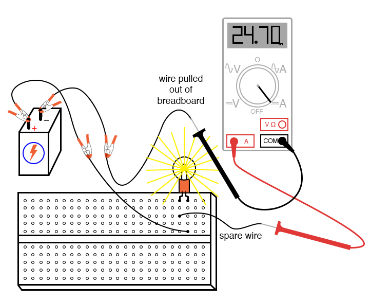
Intro Lab How to Use an Ammeter to Measure Current Basic Projects

How is ammeter connected in an electric circuit? Quora

Digital Ammeter Wiring With Current Transformer CT Coil Electrical
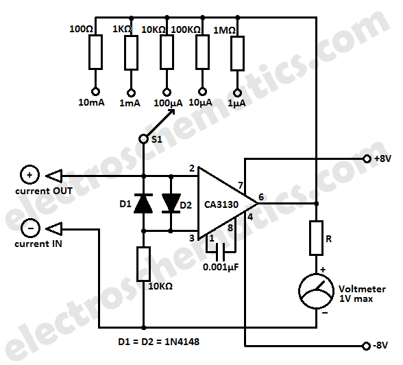
Simple Micro Ampere Meter Circuit

Ampere meter Multisim Live

Boat Ammeter Wiring Diagram

Home Electrical Wiring In Hindi

Digital Ampere Meter Wiring Diagram OnnoCenterWiki
