Ammeter Internal Circuit Diagram
Web ac voltmeters and ammeters pdf version ac electromechanical meter movements come in two basic arrangements: The internal resistance of this device is ‘0’ however in practical;
Analog Ac Ammeter Circuit Diagram Wiring Diagram
Ammeter Internal Circuit Diagram. Web draw a diagram showing an ammeter correctly connected in a circuit. Understanding ammeter circuit diagram ammeter, as we know, is a device to measure current. Understanding ammeter circuit diagram ammeter, as we know, is a device to measure current.
Web An Ammeter Is Connected In Series With The Circuit To Measure The Entire Flow Of Electrons (Current).
Web ammeter circuit diagram or ammeter diagram: The device can measure both alternating current as well as direct current. The internal resistance of this device is ‘0’ however in practical;
Web In Order To Use An Ammeter To Measure The Current At A Point In An Circuit, We Must Connect It To The Circuit In A Certain Way.
Ammeters vary in their operating principles and accuracies. Web so this device measures the current flow in ampere is named as an ammeter or ampere meter. So, let's walk through the basic steps of applying an ammeter to a circuit in real life.
Web The Schematic Diagram For Measuring The Current Of The Lamp Circuit Using An Ammeter.
Those based on dc movement designs, and those. Web ammeters measure the current through components. To measure the current going through a component, the ammeter is connected in series with the components we want to.
The Measured Current And The Internal Resistance Of The Ammeter Are The.
Web in circuit diagrams, the symbol for an ammeter is a circle with a capital a inside. Verify that the lamp lights up before connecting the ammeter in series with it. Web the following circuit represents the basic circuit diagram and the connection of the ammeter circuit in series and parallel are shown below.
Web An Ammeter Circuit Diagram Is One Of The Most Common Diagrams Used In Electrical Projects.
Web the main function of an ammeter is to measure the current in an electric circuit. Web an ammeter is a device used to measure the amount of current in an electric circuit. Consider the circuit shown in the diagram below.
Describe How A Galvanometer Can Be Used As Either A Voltmeter Or An Ammeter.
What is the principle of an ammeter and voltmeter? Web ac voltmeters and ammeters pdf version ac electromechanical meter movements come in two basic arrangements: Web draw a diagram showing an ammeter correctly connected in a circuit.
It Is Used To Measure The Current Passing Through A Circuit.
A circuit diagram user details; Web draw a diagram showing an ammeter correctly connected in a circuit. Understanding ammeter circuit diagram ammeter, as we know, is a device to measure current.
Describe How A Galvanometer Can Be Used As Either A Voltmeter Or An Ammeter.
This circuit was created by a member of the community and has no affiliation to the circuit diagram.

Analog Ac Ammeter Circuit Diagram Wiring Diagram

Why ammeter connected in series and voltmeter connected in parallel?

How is ammeter connected in an electric circuit? Quora

PPT Chapter 10 PowerPoint Presentation, free download ID1979375

Ammeter Definition and Working Principle Electrical Academia
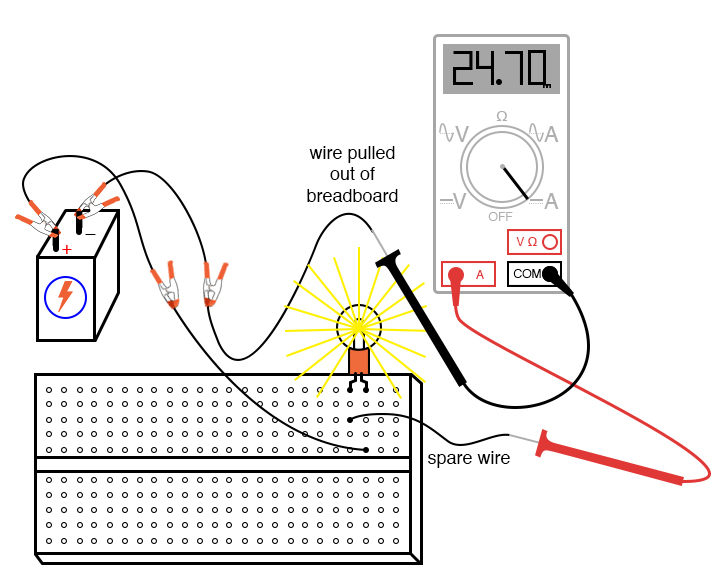
Intro Lab How to Use an Ammeter to Measure Current Basic Projects

Ammeter Wiring Diagram Car

Question Video Determining the Circuit Diagram That Represesnts the
