Ammeter In A Circuit Diagram
Web the main function of an ammeter is to measure the current in an electric circuit. Web whether you’re a student or a veteran of electrical engineering, exploring a circuit diagram with ammeter and voltmeter is important to fully understand the basics.
Ammeter Definition and Working Principle Electrical Academia
Ammeter In A Circuit Diagram. Consider the circuit shown in the diagram below. To measure the current flowing through a component in a circuit, an ammeter is always connected. They include both the full name, e.g.
Web Understanding Ammeter Circuit Diagram Ammeter, As We Know, Is A Device To Measure Current.
This circuit was created by a member of the community and has no affiliation to the circuit diagram project. Web ammeter by a circuit diagram userdetails; Web draw a diagram showing an ammeter correctly connected in a circuit.
Web The Ammeter Is A Measuring Instrument Used To Find The Strength Of Current Flowing Around An Electrical Circuit When Connected In Series With The Part Of The Circuit Being Measured
To measure the current flowing through a component in a circuit, an ammeter is always connected. Web in order to use an ammeter to measure the current at a point in an circuit, we must connect it to the circuit in a certain way. Describe how a galvanometer can be used as either a voltmeter or an ammeter.
Web On A Dc Ammeter Schematic Diagram, The Symbol For The Ammeter Is Usually Displayed At The End Of The Circuit — Usually On The Left Side Of The Diagram.
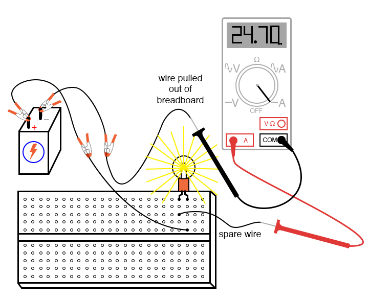
Web 1 2 3 4 measuring current and voltage current is measured using an ammeter. So, let's walk through the basic steps of applying an ammeter to a circuit in real life. Web how to use ammeters and voltmeters.
Web The Main Function Of An Ammeter Is To Measure The Current In An Electric Circuit.
Web relays form switches in your electrical circuit. In lucidchart, there are four major types of relay symbols that are labeled. Web whether you’re a student or a veteran of electrical engineering, exploring a circuit diagram with ammeter and voltmeter is important to fully understand the basics.
To Measure The Current Going Through A Component, The Ammeter Is.
They include both the full name, e.g. Consider the circuit shown in the diagram below. Ammeters measure the current through components.
Ammeters Vary In Their Operating Principles And Accuracies.
In effect, the ammeter will form a short circuit with the voltage source,. Web due to the ammeter’s very low resistance, it will “draw” a lot of current from the voltage source. Web draw a diagram showing an ammeter correctly connected in a circuit.
Web In Circuit Diagrams, The Symbol For An Ammeter Is A Circle With A Capital A Inside.
Describe how a galvanometer can be used as either a voltmeter or an ammeter.

ammeter wiring diagram
Intro Lab How to Use an Ammeter to Measure Current Basic Projects

Simple Circuit Diagram Gone Ammeter And Voltmeter Wiring Diagrams Nea

Ammeter Definition and Working Principle Electrical Academia

Analog Ac Ammeter Circuit Diagram Wiring Diagram

Ammeter Definition and Working Principle Electrical Academia

in the circuit diagram shown below,what is the reading of ideal ammeter

Simple Digital LED Ammeter Using ICL7107
