Ammeter Diagram Circuit
It shows how much current is. The ammeter must be connected in series with the component.
Ammeter Shunt Wiring Diagram For Your Needs
Ammeter Diagram Circuit. Web since ammeters are connected in series in a circuit the ammeter readings can be found in circuit diagrams by the formula of ohm’s law which is \(i =. Describe how a galvanometer can be used as either a voltmeter or an ammeter. Web draw a diagram showing an ammeter correctly connected in a circuit.
Web An Ammeter Circuit Diagram Is A Visual Representation Of The Relationship Between Electrical Components In An Electrical System.
This circuit was created by a member of the community and has no affiliation to the circuit diagram project. Web in order to use an ammeter to measure the current at a point in an circuit, we must connect it to the circuit in a certain way. Web common circuit diagram symbols ;
So, Let's Walk Through The Basic Steps Of Applying An Ammeter To A Circuit In Real Life.
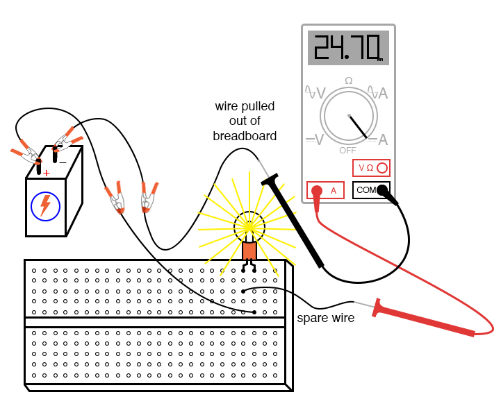
Consider the circuit shown in the diagram below. Web the schematic diagram of the arduino ammeter project is follows. Ammeters are typically represented by a circle with a letter a inside (figure 1).
It Shows How Much Current Is.
The ammeter must be connected in series with the component. Web since ammeters are connected in series in a circuit the ammeter readings can be found in circuit diagrams by the formula of ohm’s law which is \(i =. Web the current flowing through a component in a circuit is measured using an ammeter;
Web On A Dc Ammeter Schematic Diagram, The Symbol For The Ammeter Is Usually Displayed At The End Of The Circuit — Usually On The Left Side Of The Diagram.
Power source circuit diagram symbols; Web how are ammeters and voltmeters represented in a circuit? Web ammeter by a circuit diagram userdetails;
The Following Circuit Represents The Basic Circuit.
The schematic diagram shows the connection of the arduino uno with 16x2 lcd, resistor. Web draw a diagram showing an ammeter correctly connected in a circuit. The construction of ammeter can be done in two ways like series and shunt.
Understanding Ammeter Circuit Diagram Ammeter, As We Know, Is A Device To Measure Current.
Describe how a galvanometer can be used as either a voltmeter or an ammeter. Web ammeter circuit diagram. Web the main function of an ammeter is to measure the current in an electric circuit.

Ammeter Definition and Working Principle Electrical Academia
Business & Industrial Wire, Cable & Conduit Terminal Board Ammeter

in the circuit diagram shown below,what is the reading of ideal ammeter

What is a Series Circuit? Advantages, Disadvantages and Examples

Ammeter Shunt Wiring Diagram For Your Needs

Analog Ac Ammeter Circuit Diagram Wiring Diagram

Ammeter Definition and Working Principle Electrical Academia

How to Use an Ammeter to Measure Current Basic Concepts and Test
