Ammeter And Voltmeter Circuit Diagram
Individual circuit components are represented using circuit symbols. Web in a voltmeter you are measuring in paralell.
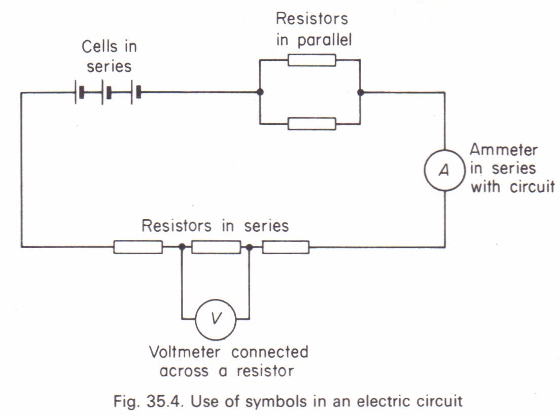
New GCSE Add'l Science OCR Gateway SB page 238
Ammeter And Voltmeter Circuit Diagram. Individual circuit components are represented using circuit symbols. Web 1 2 3 4 5 6 7 8 measuring current and voltage you need to know how to measure the current that flows through a component in a circuit and the voltage across it. Web 1 2 3 4 5 6 7 8 measuring current and voltage you need to know how to measure the current that flows through a component in a circuit and the voltage across it.
Web Draw A Schematic Circuit Diagram Consisting Battery Plug Key An Ammeter And Bulb All Connected In Series With Voltmeter Parallel The From Science Electricity.
Web wiring ammeter and voltmeter in a circuit diagram ammeter and voltmeter in a circuit diagram by clint byrd|october 8, 2017 0 comment we are all. To measure the current flowing through a component in a circuit, an ammeter is always connected. Attach the test leads correctly according to the diagram.
Web Draw A Diagram Showing An Ammeter Correctly Connected In A Circuit.
Web what is a circuit diagram draw the labelled of an electric comprising cell resistor ammeter voltmeter and closed switch or plug key which in the circuit. So you want nothing to go through the voltmeter and. Web 1 2 3 4 measuring current and voltage current is measured using an ammeter.
Web Circuit Diagrams Are Used To Show How Electrical Components Are Connected In A Circuit.
Web 1 2 3 4 5 6 7 8 measuring current and voltage you need to know how to measure the current that flows through a component in a circuit and the voltage across it. Web position the ammeter in the correct spot according to the wiring diagram. You do not want to be involved in the circuit essentially, only measure it.
It Is Connected In Series To The Element Through Which The Current Flows.
Web in a voltmeter you are measuring in paralell. Individual circuit components are represented using circuit symbols. Describe how a galvanometer can be used as either a voltmeter or an ammeter.
Voltmeters Appear In Many Circuit Analysis Questions, So It's Important That We Can Recognize Voltmeters In A Diagram As Well As Know How To Construct.
Web definition ammeter and voltmeter ammeter is a device used to measure the current in a circuit. 0.5 volts/5 amps = 100 mω exactly), then.

⭐ Circuit Diagram With Ammeter And Voltmeter ⭐

2 Wire Voltmeter Wiring Diagram Craftsian

Voltmeter With Shunt Wiring Diagram Complete Wiring Schemas
Simple Circuit Diagram Gone Ammeter And Voltmeter Electrical Wiring

Solved The Circuit Below Has The Following Values; R=60,

New GCSE Add'l Science OCR Gateway SB page 238

Why ammeter connected in series and voltmeter connected in parallel?

Ammeter Definition and Working Principle Electrical Academia
