Ad736 Circuit Diagram
Web ad736 one technology way, p.o. For instance, the common pin of an ad*6*36 is powered with a 20k/39k bridge to.
AD736 データシートおよび製品情報 アナログ・デバイセズ
Ad736 Circuit Diagram. It is laser trimmed to provide a maximum error of ±0.3 mv ± 0.3% of reading with sine wave inputs. It is laser trimmed to provide a maximum error of ±0.3 mv ± 0.3% of reading. For instance, the common pin of an ad*6*36 is powered with a 20k/39k bridge to.
For Instance, The Common Pin Of An Ad*6*36 Is Powered With A 20K/39K Bridge To.
Web the internal block diagram of the ic is given below. Web the ad737 output is negative going; Web ad736 one technology way, p.o.
The Internal Block Diagram Of Ad736 Is Shown In The Figure Below.
Web i am trying to simulate ad736 behaviour in multisim. It is laser trimmed to provide a maximum error of ±0.3 mv ± 0.3% of reading with sine wave inputs. Web to these circuits, the ad736 offers higher accuracy at an equal or lower cost.
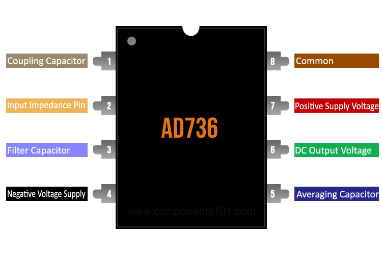
A High Impedance Fet Input (1012 Ω) That Directly Interfaces With High Z Input Attenuators And A Low Impedance.
The ad736 can compute the rms value of both ac and dc input voltages. It is laser trimmed to provide a maximum error of ±0.3 mv ± 0.3% of reading. 2 nonlinearity is defined as the maximum deviation (in percent error) from a straight line.
Web How To Use Ad736.
It is laser trimmed to provide a maximum error of ±0.3 mv ± 0.3% of reading with sine wave inputs. Web 1 accuracy is specified with the ad736 connected as shown in figure 18 with capacitor cc. The ad736 allows the choice of two signal input terminals:

Designing a True RMS to DC Converter using IC AD736

RMS / DC converter circuit composed of AD736 Basic_Circuit Circuit

AD736 RMS to DC Converter Pinout, Datasheet, Equivalent, Circuit, and Specs

AD736 datasheet(7/8 Pages) AD Low Cost, Low Power, True RMStoDC

AD736 RMS to DC Converter Pinout, Datasheet, Equivalent, Circuit, and Specs

AD736 データシートおよび製品情報 アナログ・デバイセズ
AD736 RMS to DC Converter Pinout, Datasheet, Equivalent, Circuit, and Specs

Query Regarding AD736... Q&A Energy Monitoring and Metering
