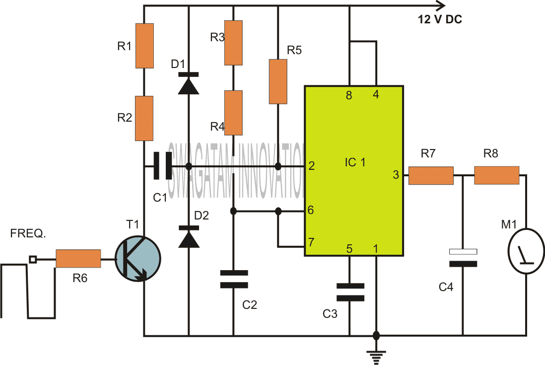
555 Capacitance Tester Circuit Diagram
From the math logic, if the. Fire alarm circuit using ic 555 timer thermistor.
555 Low Voltage Operation
555 Capacitance Tester Circuit Diagram. It is a highly stable integrated circuit that can produce accurate time. Web circuit components +5 to +9 supply voltage; Web in this tutorial we will learn how the 555 timer works, one of the most popular and widely used ics of all time.
555 Timer Circuits The Tester Consists Of An Dual Time Base Circuit 556 And A Number Of Rc.
Web 555 ic tester circuit (pcb) this 555 ic tester circuit, allows us to make sure that this integrated circuit works properly. 1kω (x2), 10kω and 100ω resistors; For a known resistors and capacitor, the frequency can be determined by a formula.
Add One Resistor To Give.
Web the frequency formula of 555 oscillator is popularly known. Web in this tutorial we will learn how the 555 timer works, one of the most popular and widely used ics of all time. It is a highly stable integrated circuit that can produce accurate time.
Speaker (8Ω) 2N3906 Pnp, 2N3904 Npn.
Web circuit components +5 to +9 supply voltage; This same test can be achieved by operating the 555. Web the 555 capacitance tester circuit diagram is a powerful tool that allows engineers to efficiently measure capacitance across a wide range of values.
Circuit Is Simple, A Lcd Is Interfaced With Arduino To Display The Measured.
Web hi , this video is to show you how to make a simple ne555 ic tester. Fire alarm circuit using ic 555 timer thermistor. From the math logic, if the.
Web 555 Capacitance Tester Circuit Diagram Posted On Nov 10, 2015 Under:
555 ic (ic under test) 8 pin ic holder 2 x 10kω resistors 2 x 1kω resistors 47μf. Web a useful circuit diagram of simple capacitance meter it will measure capacitors from 1pf to 22uf range. Web capacitor meter circuit.
Web 2 Simple Accurate Capacitance Meter Circuits.
2 simple capacitance meter circuits explained using ic 555 and 74121 homemade circuit projects. Web the circuit diagram of the 555 testing circuit is shown in the image below. Web the circuit diagram of the capacitance meter using arduino is shown in below figure.

Continuity Tester Circuit based IC 555 »

555 Capacitor Tester

Simple Continuity Testing Circuit Diagram using 555 Timer IC

555 Precision Timer Tester Circuit
2 Simple Capacitance Meter Circuits Explained Using IC 555 and IC

Electronic 555 IC Transistor Tester Valuable Tech Notes

555 Low Voltage Operation

Capacitor ESR Meter Circuit Diagram using 555 Timer
